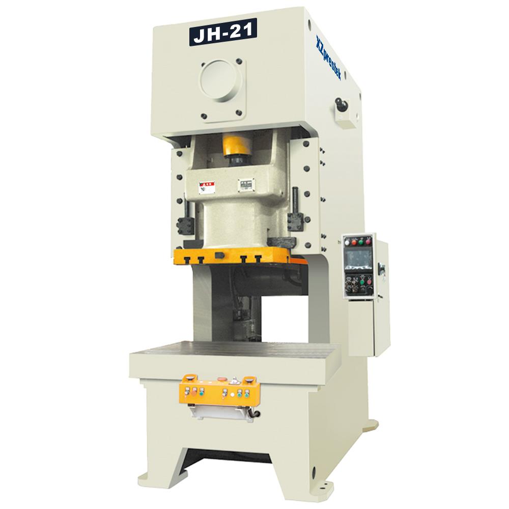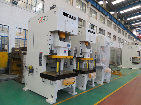
Features :
■ Universal high performance presses are widely used in the fields of aeronautics,auto,agriculture machines,electric machines,apparatuses and meters,medical equipments,electrical home appliance and hardware.
■ Welded frame with quality steel which means good rigidity.
■ Square figure long guide with six friction faces makes abrasion resistant and punching precision.
■ Hydraulic overload protector has sensitive response and reliable motion, which can protect the die when overloading.
■ Combined pneumatic clutch and brake are made of friction material, which means long service life.
■ Closed gear-driven, dipped in lube, which drives stably with low noise.
■ Slide with counter balancer, which will eliminate the clearance and improve the stability and precision.
■ Intermittent auto lubrication makes every point get fine and safe lubrication. Thus, long service life is saved.
■ PLC electric control system is safe and reliable.
■ Air cushion, photo guard, auto feeder ,speed die changing 8nd variablespeed device are optional.
Man— machine interface(option)
■ Working status clear display
■ Failure direct display
■ Maintenance text display
■ Pre-set counter
■ Strong support for functional expansion
■ TDC stop&automatic compensation
Standard accessories
■ Hydraulic overload protection device
■ Manual type, electric type lubricating device
■ Electric slide adjusting device JH-60 (inclusive) above
■ Manual slide adjusting device of Jh-1-45 (including) the following
■ The electric modulus and high display JH-60 (containing) above
■ Mechanical die height indicator JH-45 (including) the following
■ Slider and die balance device
■ The rotary cam controller
■ Pointer crankshaft angle display
■ Inteligent travel counter
■ The shockproof rubber cushion or mechanical foot slider expected device • The slider expected device
■ The main motor reversing device
■ The operating instructions
Optional accessions :
■ Pneumatic die cushion lifting device
■ Photoelectric safety device
■ Mould lighting device
■ Preload counter
■ Preset counter
■ Check how dead the next
■ The foot operated switch
■ For mold, mold clamp or mold movlng arm
■ Feeding machine, feeder, leveling machine
■ Electronic crank angle display • Air source socket
■ The air blowing device
■ The variable frequency variable speed motor
■ The fault detecting device
■ The power supply socket
■ Maintenance tools and tool kit
* Provide Customized Personalized Service
| Name | Unit | JH21-25 | JH21-45 | JH21-63 | JH21-80 | JH21-110 | JH21-125 | ||
| Nominal Pressure | - | kN | 250 | 450 | 630 | 800 | 1100 | 1250 | |
| Nominal Pressure Stroke | - | mm | 3 | 4 | 4 | 4.5 | 5 | 5 | |
| Slide Stroke Length | J | mm | 80 | 100 | 120 | 130 | 140 | 150 | |
|
No.of Strokes Per Minute |
Fixed | - | SPM | 100 | 85 | 60 | 60 | 50 | 50 |
| Variable | - | SPM | 70-100 | 50-95 | 45-75 | 40-70 | 30-60 | 30-60 | |
| Max.Die Height | D.H | mm | 250 | 270 | 300 | 330 | 350 | 380 | |
| Die Height Adjustment | G | mm | 50 | 60 | 70 | 80 | 90 | 90 | |
| Throat Depth | K | mm | 210 | 225 | 260 | 310 | 360 | 370 | |
| Distance Between Uprights | R | mm | 450 | 530 | 580 | 600 | 630 | 680 | |
| Operating Height | Z | mm | 750 | 750 | 900 | 900 | 900 | 900 | |
|
Bolster Surface Size |
L-R | E | mm | 700 | 810 | 850 | 1000 | 1100 | 1200 |
| F-B | F | mm | 400 | 440 | 500 | 600 | 680 | 700 | |
| Thickness | T | mm | 80 | 110 | 130 | 140 | 155 | 160 | |
| Blank Holes | D.H | mm | Φ120 | Φ150 | Φ150 | Φ150 | Φ160 | Φ160 | |
|
T Shaped Groove Spacing |
C | mm | 125 | 140 | 150 | 150 | 150 | 150 | |
| C1 | mm | 0 | 0 | 0 | 0 | 100 | 100 | ||
| C2 | mm | 0 | 0 | 0 | 0 | 0 | 0 | ||
|
Slide Bottom Surface Size |
L-R | P | mm | 360 | 410 | 480 | 540 | 630 | 530 |
| F-B | Q | mm | 250 | 340 | 400 | 460 | 520 | 520 | |
| Blank Holes | d | mm | Φ40x50 | Φ40x65 | Φ50x65 | Φ50x80 | Φ50x85 | Φ50x85 | |
|
T Shaped Groove Spacing |
n | mm | 0 | 0 | 0 | 210 | 300 | 300 | |
| n1 | mm | 0 | 0 | 0 | 0 | 0 | 0 | ||
| T Shaped Groove Size | W | mm | 30 | 40 | 40 | 40 | 40 | 40 | |
| V | mm | 18 | 22 | 22 | 22 | 22 | 22 | ||
| X | mm | 18 | 22 | 27 | 27 | 27 | 27 | ||
| Y | mm | 12 | 18 | 18 | 18 | 18 | 18 | ||
| Main Motor | Power | - | kW | 3 | 4 | 5.5 | 7.5 | 7.5 | 11 |
| Slide Motor | Power | - | kW | - | - | 0.5 | 0.5 | 0.5 | 0.5 |
| Overall Dimension | L-R | A | mm | 857 | 990 | 1090 | 1186 | 1325 | 1378 |
| F-B | B | mm | 1365 | 1410 | 1590 | 1774 | 1830 | 1931 | |
| Height | H | mm | 2180 | 2320 | 2730 | 3085 | 3110 | 3184 | |
| Optional Cushion | Cushion Force | - | kN | 30 | 45 | 60 | 60 | 100 | 100 |
| Stroke | - | mm | 80 | 50 | 50 | 50 | 70 | 70 | |
No.of Strokes
Per Minute
Bolster Surface
Size
T Shaped
Groove Spacing
Slide Bottom
Surface Size
T Shaped Groove
Spacing
Name
Unit
JH21-160
JH21-200
JH21-250
JH21-315
JH21-400
Nominal Pressure
-
kN
1600
2000
2500
3150
4000
Nominal Pressure Stroke
-
mm
6
6
6
8
10
Slide Stroke Length
J
mm
160
160
200
250
250
Fixed
-
SPM
50
50
30
30
25
Variable
-
SPM
30-60
25-50
24-40
25-40
20-25
Max.Die Height
D.H
mm
400
450
500
550
550
Die Height Adjustment
G
mm
110
110
110
120
120
Throat Depth
K
mm
380
400
430
430
510
Distance Between Uprights
R
mm
780
820
920
1000
900
Operating Height
Z
mm
900
900
1000
1000
1000
L-R
E
mm
1300
1400
1400
1500
1800
F-B
F
mm
740
780
840
840
1000
Thickness
T
mm
165
170
175
180
180
Blank Holes
D.H
mm
Φ180
Φ200
Φ200
Φ220
Φ250
C
mm
150
150
150
150
200
C1
mm
150
150
150
150
200
C2
mm
0
0
0
0
0
L-R
P
mm
800
800
880
950
950
F-B
Q
mm
580
590
650
700
700
Blank Holes
d
mm
Φ65x90
Φ65x90
Φ65-100
Φ65x110
Φ65x110
n
mm
320
320
300
320
320
n1
mm
110
110
150
160
160
T Shaped Groove Size
W
mm
46
46
46
46
45
V
mm
28
28
28
28
28
X
mm
28
28
28
28
28
Y
mm
20
20
20
20
20
Main Motor
Power
-
kW
15
18.5
22
30
37
Slide Motor
Power
-
kW
0.75
0.75
1.1
1.5
1.5
Overall Dimension
L-R
A
mm
1513
1540
1622
1920
1800
F-B
B
mm
2123
2177
2700
2700
3220
Height
H
mm
3300
3380
3865
4350
4600
Optional Cushion
Cushion Force
-
kN
145
145
145
145
145
Stroke
-
mm
80
80
80
80
80
